


Accurate control valve sizing and pressure drop calculation isn’t just another technical process that factory engineers do. Doing this is crucial to establishing stable flow, preventing energy loss, and protecting equipment from damage.
If not done properly or skipped completely, flow systems result in noise, vibration, or unstable control. These are common issues that come from assumptions or guesses about the flow rate or pressure conditions that particular systems actually need.
So, read on as this guide explains how to size a control valve step by step. It also breaks down how pressure drop is calculated and why it matters in various industries and applications.

Why Control Valve Selection Matters
Control valves, from the name itself, regulate flow, pressure, and temperature in a system. Their performance directly affects process stability and efficiency.
If a valve is too small, it restricts flow and creates excessive pressure loss. If it is too large, control becomes unstable and difficult to manage.
Proper selection ensures smooth operation and longer equipment life. This is why engineers focus on both flow capacity and pressure conditions during design.
Understanding the Control Valve Cv Definition
The Cv value is the foundation that sets the final decision when selecting the right valves. It represents the flow capacity of a valve under specific conditions.
That’s because not all systems or industries require the same type of valve.
In simple terms, Cv shows how much fluid can pass through the valve at a given pressure drop. A higher Cv means higher flow capacity.
The control valve Cv is critical because it links flow rate, pressure drop, and valve size. Without this value, accurate selection is not possible.
How to Size a Control Valve Step by Step
The process of how to size a control valve follows a clear sequence.
Step 1: Define Process Conditions
Start by identifying key parameters. These include flow rate, inlet pressure, outlet pressure, temperature, and fluid type.
Fluid properties such as density and viscosity also affect sizing. These factors influence how the fluid behaves inside the valve.
Step 2: Determine Required Flow Rate
Flow rate is usually given in process data sheets. It defines how much fluid must pass through the valve.
Both maximum and minimum flow rates should be considered. This ensures the valve performs well under all operating conditions.
Step 3: Estimate Pressure Drop
Pressure drop is the difference between the inlet and outlet pressures. It drives the flow through the valve.
A typical design approach allocates a portion of system pressure to the valve. This helps maintain stable control.
Step 4: Perform Control Valve Sizing Calculation
Using flow rate and pressure drop, the Cv value is calculated. This step is the core of the valve sizing calculation process.
Engineers often use standard formulas or a control valve sizing calculator to simplify this step. These tools reduce manual errors and save time.
Step 5: Select Valve Size and Type
Once Cv is known, the appropriate valve size can be selected. The chosen valve should operate within a stable range.
Valve type also matters. Globe valves are common for precise control, while other types may suit specific applications.
How to Calculate Pressure Drop Across a Control Valve
Understanding how to calculate pressure drop across a control valve is essential for accurate sizing. Pressure drop determines how much energy is used to move fluid.
The basic principle is simple. It is the difference between upstream and downstream pressure as shown in the formula below:

This formula stands for:
- ΔP = pressure drop
- P1 = inlet pressure
- P2 = outlet pressure
Sample Calculation and What It Means
Consider a system where the inlet pressure is 10 bar, and the outlet pressure is 6 bar. The pressure drop is calculated by subtracting the outlet pressure from the inlet pressure.
This gives a pressure drop of 4 bar.
This result means the valve is using 4 bars of energy to control the flow. If the pressure drop is too low, the valve may struggle to regulate flow. If it is too high, it may cause energy loss and wear.
IMPORTANT: Various systems involve more variables. These include pipe friction, elevation changes, and fittings.
Key Factors Affecting Pressure Drop
These factors affect how fluid moves through the system and how much energy is lost.
| Factor | Description | Impact on Pressure Drop |
| Fluid Density | Refers to how heavy the fluid is | Higher density can increase pressure drop under certain flow conditions |
| Fluid Viscosity | Measures the fluid’s resistance to flow | Higher viscosity increases resistance and leads to higher pressure loss |
| Pipe Length | Total distance the fluid travels | Longer pipes create more friction, increasing pressure drop |
| Pipe Fittings | Includes bends, valves, and connectors | Each fitting adds resistance and contributes to pressure loss |
| Flow Velocity | Speed of fluid movement | Higher velocity increases friction and raises pressure drop |
Practical Approach to Pressure Drop Allocation
Engineers often assign a portion of the total system pressure to the valve. This ensures stable control without excessive energy loss.
A common approach is to use a moderate pressure drop. Too low leads to poor control, while too high wastes energy.
Choked Flow and Its Impact on Valve Sizing
Choked flow occurs when fluid velocity reaches a critical limit. At this point, increasing the pressure drop does not increase the flow rate.
This condition is common in gas and high-pressure liquid systems. It can lead to noise, vibration, and potential damage.
Using Software and Tools for Accurate Sizing
Manual calculations can be complex and time-consuming. This is why many engineers rely on valve sizing software.
These tools handle complex formulas and provide quick results. They also reduce the risk of calculation errors.
A control valve sizing calculator is useful for initial estimates. For detailed design, state-of-the-art software offers more precise analysis.
Digital tools also allow the simulation of different operating conditions. This helps in selecting the best valve for varying loads.
Engineering Support and Practical Experience
Accurate valve selection requires both calculation and experience. GOWIN provides support based on real operating conditions.
With 16 years of fluid control experience, the team assists in early-stage selection. This includes reviewing data sheets and performing Cv calculations.
Custom design and drawing support are also available. This helps meet specific project requirements that standard products cannot handle.
Founded in 2007, GOWIN serves industries such as oil and gas, chemical, power, and water systems. The company maintains strong relationships with global clients through consistent service and product quality.
GOWIN operates under ISO9001, ISO14001, and ISO45001 standards, along with certifications including API6D, API607, API6FA, and TS. These certifications reflect its focus on safety, quality, and environmental compliance.
Distributors benefit from this support by improving accuracy and reducing risk. Engineering input ensures outstanding performance in actual service.

Final Thoughts on Valve Sizing and Pressure Drop
Control valve performance depends on correct sizing and proper pressure drop selection. These factors work together to ensure stable and efficient operation.
Understanding flow behavior, system conditions, and valve characteristics leads to better decisions. It also helps avoid common design errors.
With the right approach, control valves can deliver precise regulation and long service life in demanding applications.
High-performance control valves engineered to international standards (ASME, API, JIS, BS, DIN). Available in sizes from 3/4″ to 72″ with pressure ratings up to 42.0 MPa. Suitable for water, oil, and gas applications with temperature range from -196℃ to 650℃.
Explore Product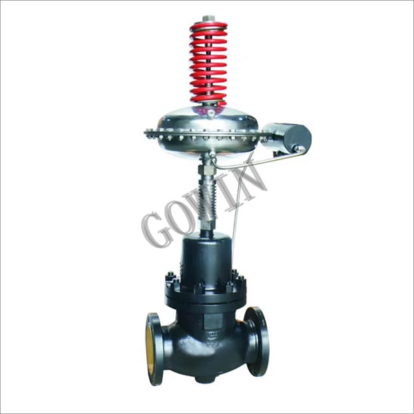


 CHINA
CHINA LIBERIA
 FRANCE
 BARBADOS
 KIRIBATI

