


Quick Answer
Read a butterfly valve position from the operator first, then confirm it against the disc and the approved drawing. A lever parallel to the pipe usually means open; perpendicular usually means closed. Gearboxes and actuators use pointers or OPEN/SHUT marks. An indicator confirms position, not safe isolation or zero leakage.
What Do Open and Closed Look Like on a Lever Valve?

The lever is the quickest visual check on a manual butterfly valve. In the common convention, a lever aligned with the pipe shows an open disc, while a lever across the pipe shows a closed disc. The lever turns through about 90 degrees between the two states.
That convention is useful, but it is not universal proof. An extension lever, a vertical pipe or a valve installed with a different stem orientation can change what “parallel” looks like from the platform. The butterfly valve position should be read from the operator and the pipe together, not from the handle alone.
Start with the valve’s manual butterfly valve page or the wider butterfly valve category to identify the operator style. Then use the model drawing to see how the lever relates to the disc. A buyer should not assume that a lever photo from another model applies to the quoted valve.
How Do Gearboxes and Actuators Show Position?

A gear operator usually has a position pointer and a plate marked OPEN and SHUT. The pointer follows the gearbox output, so it should track the disc through the full quarter turn. Some gearboxes also show a small travel scale. Read the mark that corresponds to the actual model, not a generic label on a different housing.
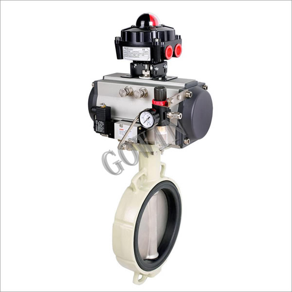
A pneumatic, electric or hydraulic actuator may use a top-mounted visual indicator. The indicator can be a dome, a pointer or a slotted disc. Limit switches and a position transmitter may also send feedback to the control system. That feedback is useful, but it still depends on correct setup and calibration.
| Position source | What it shows | What it does not prove |
|---|---|---|
| Lever or handle | Operator angle | That the disc has reached the seat |
| Gearbox pointer | Gearbox output position | That the line is isolated |
| Actuator visual indicator | Actuator travel | That the control signal is correct |
| Limit switch or transmitter | Electrical feedback | Zero leakage or a safe line break |
For an automated valve, compare the pneumatic butterfly valve arrangement with the electric butterfly valve and gear-operated butterfly valve pages. The operator hardware changes the way position is displayed, but the disc remains the final mechanical reference.
What Does an Intermediate Position Mean?
A lever at roughly 45 degrees, or an actuator indicator between OPEN and CLOSED, means the disc is partly open. That may be intentional for flow control, but a standard butterfly valve is not automatically a precise control valve. The position may also be a travel stop, a partially engaged actuator or a fault.
Do not treat an intermediate reading as a safe throttling setting without checking the duty. The disc shape and the resulting flow curve affect how the valve behaves. If the process needs repeatable modulation, read the overview of pneumatic valve types and confirm whether a control valve is more appropriate than a butterfly valve used as an isolation device.
The important buyer question is not “Can the disc sit halfway?” It is “Does the selected model, actuator and control system support the required position without unacceptable vibration, noise or seat damage?” The butterfly valve position answer belongs in the specification, not in a generic diagram.
Why Can Two Indicators Disagree?

Two indicators can disagree when the actuator has been mounted in a different orientation, the limit-switch cam has slipped, or the stem-to-disc connection is not where the installer expects. A loose pointer can also move independently of the shaft. The valve may be open while the switch says closed, or the switch may be correct while the pointer is wrong.
Pipe orientation adds another source of confusion. A lever that looks parallel on a horizontal run may look across the pipe from a different walkway. An extension stem can put the operator far from the disc. The lug versus wafer butterfly valve comparison explains how body style changes installation, but it does not replace the model-specific position check.
If the indicators disagree, stop and use the assembly drawing. Do not force the operator to make the pointer match. Forcing a valve can damage the seat, the stem or the actuator linkage. Record the actual lever or indicator angle and the switch state before asking for help.
How Do You Verify Position Against the Drawing?
The approved assembly drawing should show the stem orientation, the disc orientation, the operator mounting and the position marks. It may also show the actuator’s air or power failure position. Use that drawing to answer three questions: what does the operator do when the valve opens, where should the pointer sit, and what should the feedback switch report?
On a manual valve, the stem flats or slot can provide a second reference because they normally align with the disc. On an automated valve, remove power or air only under the site’s safe procedure and confirm the actuator’s failure mode. Never open a line or loosen a stem packing just to see the disc.
GOWIN’s centric construction butterfly valve page shows a compact body with lever, gear or electric operation. That page describes a product family, not the position of every installed valve. The guide to how a pneumatic butterfly valve works is useful background, while the drawing settles the actual assembly.
What Should You Send the Supplier?
Send the model, size, pressure class, operator type, mounting orientation and a photo or sketch of the installed arrangement. Add the drawing revision and the position-switch logic if feedback is part of the package. If the valve is already installed, include the observed lever angle, pointer position and switch state.
For a replacement, send the tag number and the original datasheet as well as the pipe orientation. A wafer butterfly valve may fit between flanges differently from a lug body, and an actuator can be rotated during installation. The butterfly valve size guide helps separate size from operator position, but the two must be checked together.
The lever versus gear-operated comparison and the actuation methods guide can help the project team choose a readable operating method. For high-cycle or automated service, the triple eccentric butterfly valve may be a different starting point, but its position indication still needs the same drawing review.
Standard: ASME, API, JIS, BS, DIN, GB, JB, HG
Conclusion
Butterfly valve position is easiest to read when the lever, pointer, actuator indicator and feedback signal tell the same story. Use the common lever convention for a first look, then confirm the disc and operator against the approved drawing. If the signals disagree, do not force the valve or assume the line is isolated.
The buyer’s job is to make position readable and verifiable before the valve arrives. Specify the operator, mounting orientation, feedback type and drawing requirements in the RFQ. That prevents a small indicator mismatch from becoming a maintenance problem after installation.
Send the medium, size, operating pressure and temperature, and the relevant drawing for a duty-specific quotation.


 CHINA
 LIBERIA
 FRANCE
 BARBADOS
 KIRIBATI


