

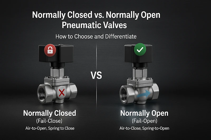
You can differentiate these pneumatic valve types by their default position when no air pressure is applied. Normally closed pneumatic valves block flow, making them ideal for safety and containment. Normally open valves allow flow, making them suitable for processes where continuity is critical. The choice depends on the fail-safe behavior you need during a power or air failure.
What is a Normally Closed Pneumatic Valve?
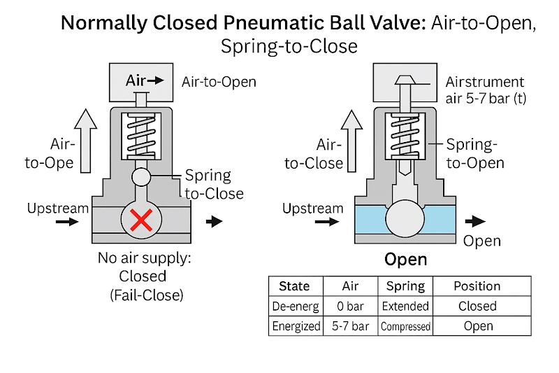
A normally closed pneumatic valve remains shut when no compressed air is supplied to the actuator. This configuration uses spring force to keep the valve element sealed against the seat, completely blocking flow through the valve body.
The operation principle is air-to-open, spring-to-close. With no air supply, the valve stays closed. Apply air pressure and the valve opens. Remove air and spring returns the valve to closed position.
The normally close sanitary pneumatic ball valve design ensures the ball element stays rotated to block the flow path. When compressed air enters the actuator chamber, it overcomes spring force to rotate the ball 90 degrees, opening the flow path. This configuration is also called “air-to-open” or “spring-return-to-close.
What is a Normally Open Pneumatic Valve?
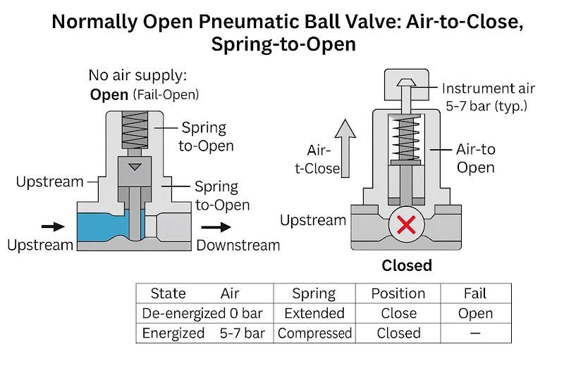
A normally open pneumatic valve maintains an open flow path when no compressed air is supplied to the actuator. The spring mechanism positions the valve element away from the seat, allowing continuous flow until air pressure closes the valve.
The operation principle is air-to-close, spring-to-open. With no air supply, the valve stays open. Apply air pressure and the valve closes. Remove air and spring returns the valve to open position.
This configuration keeps the flow path clear during normal operation. Compressed air must be continuously supplied to maintain the closed position. When air supply stops, spring force immediately returns the valve to its open state.
Differentiating Between Normally Closed and Normally Open Pneumatic Valves
The main way to differentiate is by understanding their default position and behavior without air pressure. Here’s a table showing the key differences:
| Feature | Normally Closed (NC) | Normally Open (NO) |
| Default Position | Closed without air supply | Open without air supply |
| Spring Action | Spring closes valve | Spring opens valve |
| Air Requirement | Air pressure opens valve | Air pressure closes valve |
| 2-Port Behavior | Blocks inlet to outlet flow | Allows inlet to outlet flow |
| 3-Port Behavior | Supply port closed, exhaust connects to output | Supply port connects to output, exhaust closed |
| Actuation Method | Air-to-open, spring-to-close | Air-to-close, spring-to-open |
Physical identification methods
Most valves show their configuration through clear markings. Check for nameplate markings like “NC,” “NO,” “Air to Open,” or “Air to Close” to identify the type without testing.
Spring position in single-acting actuators reveals the configuration. Springs positioned to push the valve closed indicate normally closed setup. Springs positioned to push the valve open indicate normally open configuration.
The air control sanitary pneumatic ball valve typically shows clear actuator markings and visible spring arrangements. Check the actuator housing for spring location and air port positioning to determine fail-safe behavior.
Port configuration differences
2-port valves control simple on/off flow. Normally closed valves block flow from inlet to outlet when de-energized because the internal element physically seals the flow path. Normally open valves allow continuous flow from the inlet to the outlet when de-energized.
3-port valves manage supply air, exhaust air, and output to equipment like pneumatic cylinders. Normally closed keeps the supply port shut while connecting the exhaust port to the output port. This vents downstream pressure while preventing new air from entering. Normally open connects supply port to output port while blocking exhaust to maintain system pressure.
This configuration significantly affects the operation of fail-safe valve systems. The choice determines whether downstream equipment loses pressure (NC) or maintains pressure (NO) during air supply failures.
Operational testing methods
The most reliable differentiation involves safely observing the valve’s response to air pressure changes. Apply low air pressure and watch the valve move, then remove the air pressure and note the fail-safe position.
The behavior of normally open and normally closed valves becomes immediately apparent during testing. Normally closed valves need air pressure to open and automatically return to closed when air stops, while normally open valves need air pressure to close and automatically return to open when air stops.
This testing method provides definitive identification when nameplate markings are unclear. Always use proper safety procedures when testing with compressed air. Start with low pressure and ensure proper ventilation. The valve’s actual response reveals its true configuration and pneumatic actuator types being used.
Choosing the Right Configuration
When selecting valve configurations, weigh these factors:
- Safety in failure: Use normally closed if uncontrolled flow is hazardous (spills, leaks, pressure buildup). Choose normally open if flow loss is riskier (overheating, fire protection failure).
- Duty cycle: Go with normally closed if the valve stays shut most of the time to cut air and energy use. Use normally open if flow is continuous with rare shutoff.
- Process priority: Emergency cooling, fire suppression, and life safety usually need normally open. Hazardous containment typically needs normally closed.
- Compliance: Follow codes and standards that may dictate fail-safe positions, especially in chemical, oil and gas, pharmaceutical, and food industries.
- System integration: Emergency shutdowns pair naturally with normally closed valves. Process controls may prefer normally open for flexibility and actuator types that maintain flow during short power losses.
Conclusion
Choosing the right valve configuration is the first step toward building a safer and more efficient system. The next step is matching those choices to your industry’s standards, operating environment, and long-term performance goals.
GOWIN Industrial Valve has engineers to evaluate these factors and recommend the best pneumatic ball valve setup for your application. From initial specification to product selection, our team ensures your system meets both safety and efficiency needs.
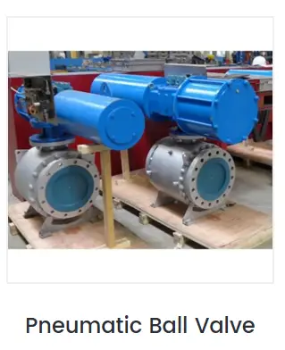
Explore our full range of pneumatic ball valves, or contact a GOWIN specialist to discuss the configuration that best suits your operation.


 CHINA
CHINA LIBERIA
 FRANCE
 BARBADOS
 KIRIBATI

