

A Practical Guide to Pneumatic Control Valve Calibration for Peak Performance
Calibrating a pneumatic control valve is essential for precise process control, equipment safety, and system efficiency. The process ensures that the valve opens and closes at the right signal pressures, avoiding production issues or safety hazards.
In this guide, you will learn how to calibrate a pneumatic control valve step by step, understand the required tools, and discover best practices to extend valve life and performance.
Why Is Calibration Important?

Calibration ensures that the valve responds accurately to control signals from the plant’s control system. It is critical because:
- Efficiency: A calibrated valve provides correct flow control, minimizing process variation and energy waste. Incorrect calibration can lead to unstable process conditions and poor product quality.
- Safety: Improperly calibrated valves may cause pressure surges, leaks, or equipment failure, posing risks to personnel and plant operations.
- Longevity: Regular calibration prevents undue stress on valve actuators, seals, and stems, helping avoid premature wear and costly unplanned shutdowns.
Tools and Equipment You Will Need

Before starting, gather all required tools for pneumatic control valve calibration:
- Instrument air supply (clean and dry)
- Precision air pressure regulator (3–15 PSI signal simulation)
- Reference standard pressure gauge
- Multimeter with probe and leads
- Tubing and fittings
- HART communicator (for smart positioners)
- Manufacturer’s datasheet for correct specifications
GOWIN valves are compatible with standard calibration tools used worldwide. Their actuators and positioners are designed to work with common 3–15 PSI systems, making setup straightforward. GOWIN’s engineering team, with expertise from institutions like Lanzhou University of Technology, also offers on-site guidance and maintenance support in high-demand regions such as Africa.
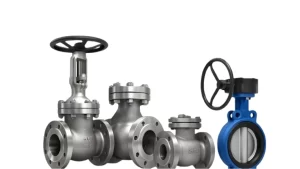
High-performance control valves engineered to international standards (ASME, API, JIS, BS, DIN). Available in sizes from 3/4″ to 72″ with pressure ratings up to 42.0 MPa. Suitable for water, oil, and gas applications with temperature range from -196℃ to 650℃.
Explore Product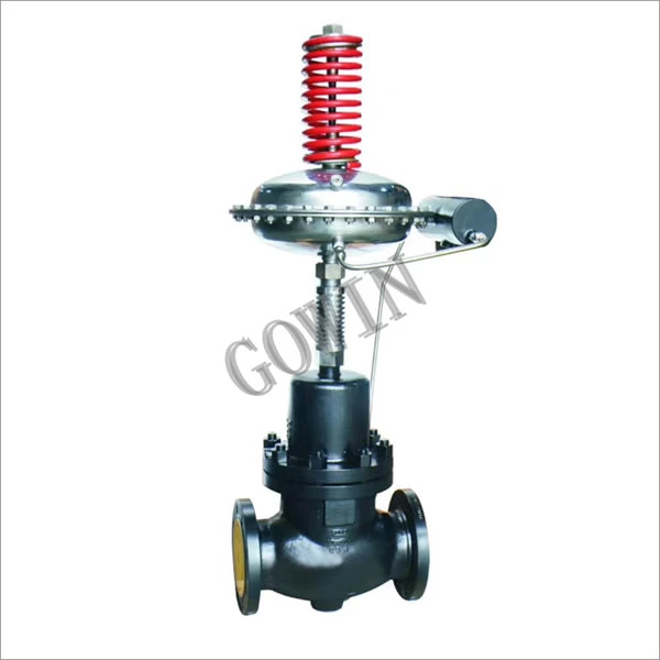
Step-by-Step Calibration Process
Follow these steps to ensure accurate pneumatic control valve calibration. Always perform lockout/tagout, verify isolation, and review the manufacturer’s datasheet before starting.

Step 1: Isolate the Valve
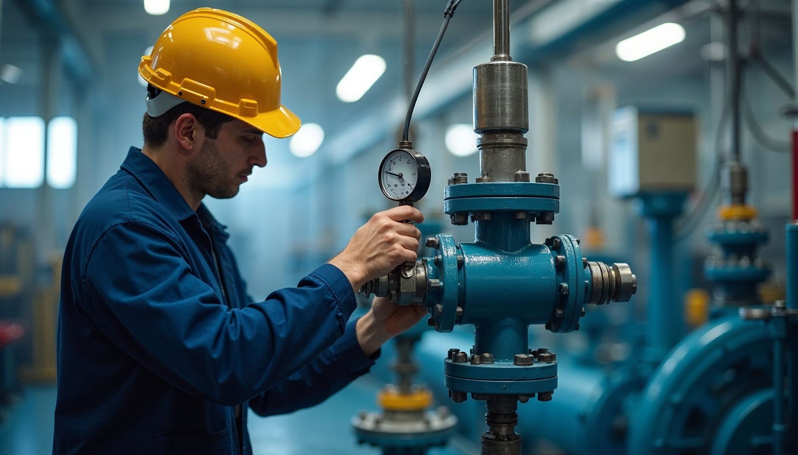
Shut down the control loop, place the controller in manual mode, and depressurize the pipeline. Disconnect both pneumatic and electrical connections. Verify zero pressure using a gauge and apply lockout/tagout tags to prevent accidental energizing. Make sure the control valve with pneumatic actuator is fully isolated and safe to handle.
Step 2: Connect the Calibrator
Secure the control valve with pneumatic actuator in a stable bench setup. Connect a precision regulator, a certified reference pressure gauge, and tubing with leak‑free fittings. For valves with a pneumatic control valve positioner, ensure a stable 20 PSI supply and confirm correct airflow direction.
Step 3: Check Zero and Span
Gradually apply 3 PSI to simulate a 0% signal and confirm the stem is at the fully closed position. Adjust the zero screw if needed. Increase pressure slowly up to 15 PSI to achieve 100% stroke and adjust the span screw accordingly. Verify travel at 25%, 50%, and 75% to ensure linear response.
Step 4: Make Adjustments
Repeat zero and span tuning until the valve moves accurately at all setpoints. For smart positioners, connect a HART communicator to send 4–20 mA signals, perform auto‑calibration if supported, and record the “as found” and “as left” values for maintenance traceability.
Common Mistakes to Avoid

- Skipping bench set verification leads to incorrect spring compression and improper valve travel.
- Ignoring datasheet specifications can result in using the wrong actuator pressure range or stem connector settings.
- Forgetting to record “as found” and “as left” values removes traceability for audits and future maintenance.
- Using uncalibrated gauges or regulators creates inaccurate readings and unsafe valve operation.
- Neglecting lockout/tagout procedures before work can cause serious safety hazards.
Many facilities prevent these errors by working with GOWIN Industrial Valve, whose engineers provide on‑site calibration, documentation templates, and training. GOWIN’s team also ensures compliance with standards such as ISO 5208 and IEC 60534 while supporting clients in regions with high on‑site service demand.
How Often Should You Calibrate?

Calibration frequency depends on process conditions, valve criticality, and regulatory requirements. Most facilities calibrate control valves every 6–12 months to meet ISO 5208 and IEC 60534 standards. Critical service valves in refineries or chemical plants often require quarterly checks due to harsh conditions. GOWIN provides scheduled maintenance with field engineers who ensure proper documentation, benchmarking of as‑found/as‑left data, and training for in‑house staff.
FAQs
Q1: How do you calibrate a pneumatic control valve?
You use a regulated air supply and pressure gauge to set zero and span points, adjusting the positioner until the valve strokes correctly at 3–15 PSI.
Q2: What is a pneumatic control valve positioner?
It is a device that adjusts the valve actuator to match the control signal, improving accuracy and response.
Q3: How often should you calibrate a pneumatic control valve?
Most valves are calibrated every 6–12 months, or sooner for safety-critical applications.
Q4: Can all valves use the same calibration tools?
Yes, most industrial valves, including GOWIN valves, work with standard regulators and gauges.
Q5: Why is bench setting important before calibration?
It ensures the actuator spring preload is correct, so the valve responds accurately to signal pressure.
Final Thoughts
Knowing how to calibrate a pneumatic control valve ensures safe and efficient plant operations. With the right tools and a systematic approach, calibration becomes a straightforward task. If you need expert support, GOWIN Industrial Valve offers on-site technical guidance, precision manufacturing, and long-term maintenance solutions to keep your valves performing at their best. For more details about pneumatic control valve calibration or technical assistance, visit GOWIN Industrial Valve. Our specialists provide professional guidance, on-site services, and maintenance programs to keep your valves performing at their best.


 CHINA
CHINA LIBERIA
 FRANCE
 BARBADOS
 KIRIBATI

